3. Product Overview
3.1 Product Introduction
- The Walker Tienkung series robots are full‑size, fully electric, humanoid running robots jointly developed by UBTECH Robotics Corp., Ltd. and Beijing Humanoid Robotics Innovation Center Co., Ltd. They feature a highly bionic torso configuration and human‑like motion control capabilities. The robots can be equipped with up to 42 degrees of freedom. Each arm can be configured with a 7‑DoF robotic arm, and the wrist can be fitted with a high‑precision six‑axis force sensor, as well as dexterous five‑finger hands.
- The Walker Tienkung series robots can stand, walk, run, and perform multiple specific actions. They can stably adapt to complex terrains such as slopes and sandy ground and exhibit excellent dynamic balance and disturbance rejection performance. Equipped with powerful joint actuators, a high‑precision IMU, and a dual‑battery quick‑swap system, the robots can achieve a continuous operating time of more than 3.5 hours.
- In addition, Walker Tienkung · Voice & Vision and Walker Tienkung · Embodied Intelligence can integrate a voice module and a large language model for voice interaction, supporting natural language interaction. The overall computing power can reach up to 550 TOPS.
- As a general‑purpose humanoid robot platform, the entire Walker Tienkung series provides open interfaces for all joints and sensors, facilitating industry‑specific secondary development to enable innovative applications in research, education, and other scenarios.
3.2 Key Features
- Adaptive locomotion on complex terrain: Capable of stable walking on irregular terrains such as slopes and sandy ground.
- Humanoid running capability: Supports running motions.
- Dynamic balance control: Able to resist external disturbances in real time and maintain posture stability.
- Motion control modes: Reinforcement learning‑based motion control modes have been deployed.
- Voice interaction control: Equipped with a voice module and supports user‑deployed large‑scale voice models to enable natural voice commands and interactions.
- Open interface design: Provides full‑body joint and sensor interfaces, supporting teleoperation, data acquisition, and secondary development.
3.3 Application Scenarios
This product is designed for use in scientific research and educational scenarios.
warning
- Users may explore additional application scenarios through secondary development but must ensure compliance with the laws, regulations, safety requirements, and other qualifications applicable to the specific scenarios.
- For any use beyond scientific research and education, the user shall bear all corresponding responsibilities.
- It is strictly prohibited to use the factory‑configured product directly in public places without safety protection or in high‑risk environments (such as rescue operations or medical care).
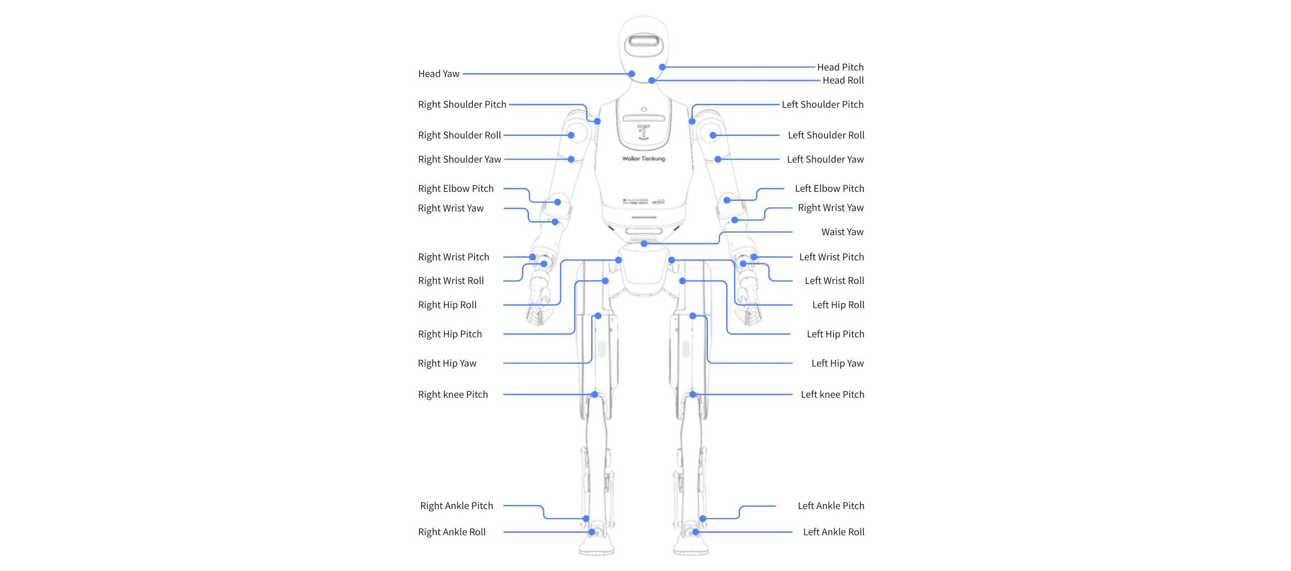
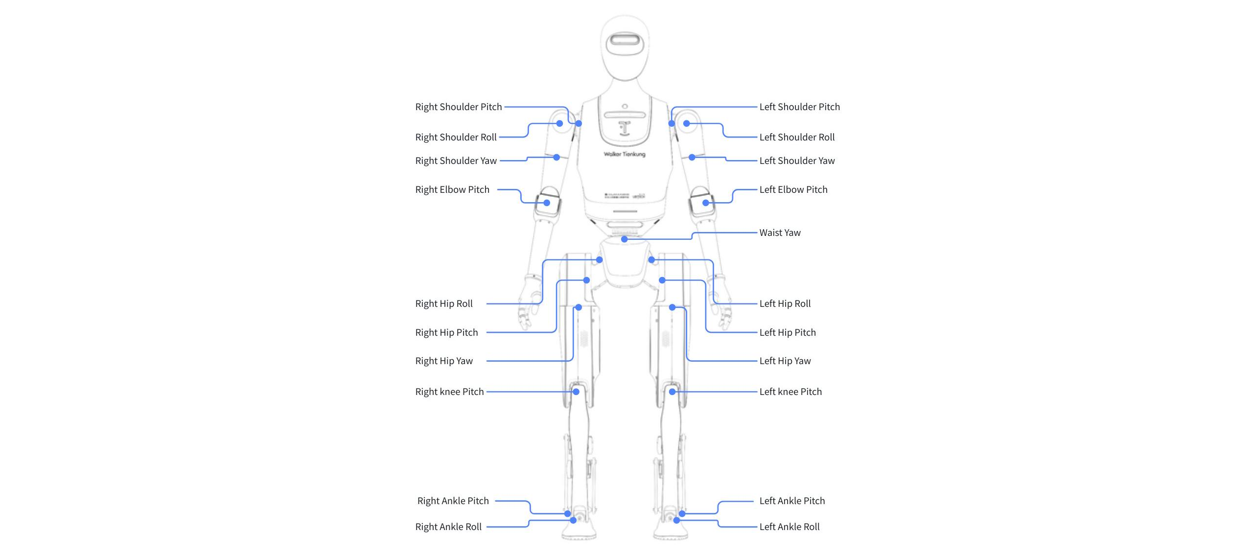
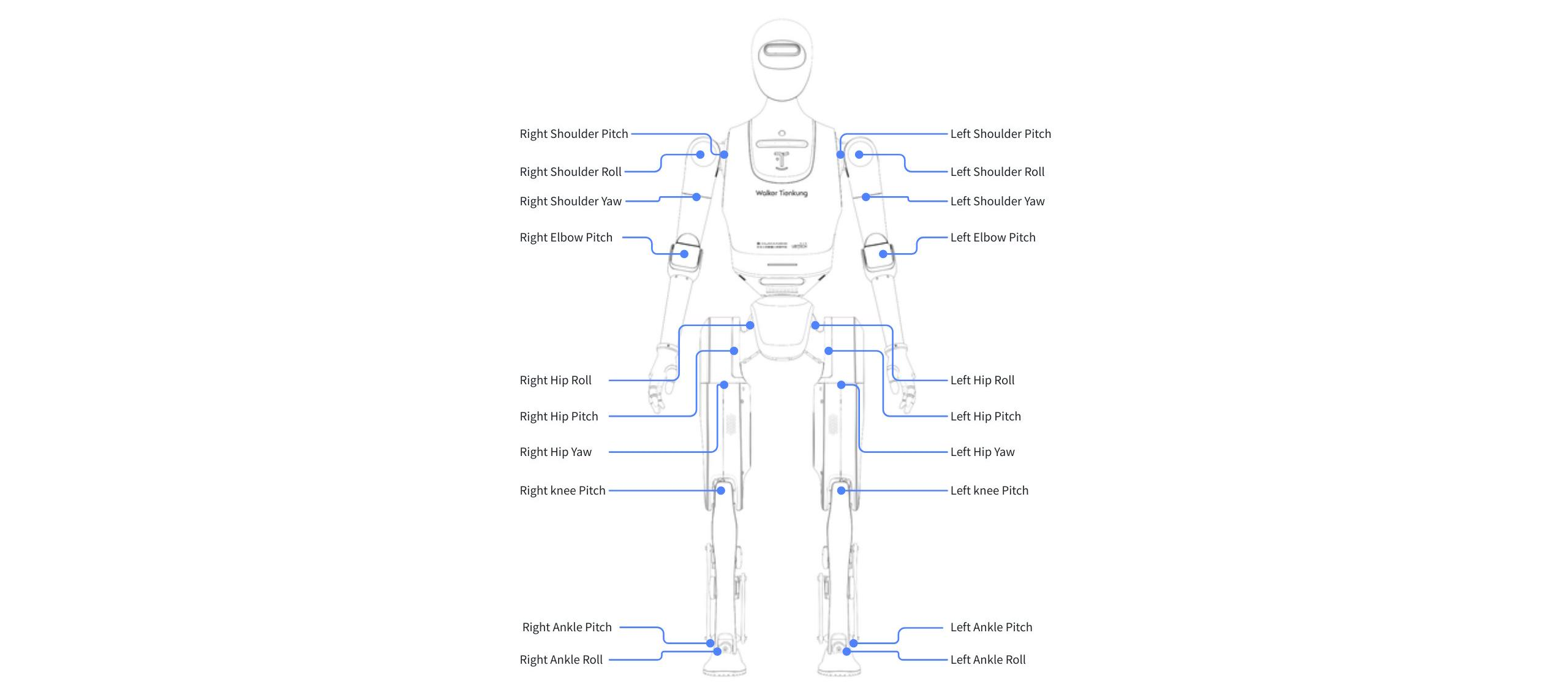
3.4 Walker Tienkung Joint Layout
- Walker Tienkung · Embodied Intelligence
- Walker Tienkung · Voice & Vision
- Walker Tienkung
3.5 Walker Tienkung Full‑Body Joint Parameters
| Name | Motion Range (°) | Torque Constant (Nm/A) | Max Speed (rpm) | KP/KD Range | Rated Torque (Nm) | Peak Torque (Nm) | Joint ID | Applicable Models |
|---|---|---|---|---|---|---|---|---|
| Head Roll | -26° ~ +26° | 2.16 | 64 | Kp: 0~2000 Kd: 0~300 | 3 | 9 | 1 | Walker Tienkung · Embodied Intelligence |
| Head Pitch | -25° ~ +25° | 2.16 | 64 | Kp: 0~2000 Kd: 0~300 | 3 | 9 | 2 | Walker Tienkung · Embodied Intelligence |
| Head Yaw | -90° ~ +90° | 2.16 | 64 | Kp: 0~2000 Kd: 0~300 | 3 | 9 | 3 | Walker Tienkung · Embodied Intelligence |
| Waist Yaw | -170° ~ +170° | 3.207 | 88 | Kp: 0~2000 Kd: 0~300 | 35 | 91 | 31 | Walker Tienkung · Embodied Intelligence / · Voice & Vision |
| Left Shoulder Pitch | -170° ~ +170° | 3.207 | 88 | Kp: 0~2000 Kd: 0~300 | 35 | 91 | 11 | All Walker Tienkung models |
| Left Shoulder Roll | -15° ~ +150° | 3.37 | 120 | Kp: 0~2000 Kd: 0~300 | 20 | 60 | 12 | All Walker Tienkung models |
| Left Shoulder Yaw | -170° ~ +170° | 2.43 | 73 | Kp: 0~2000 Kd: 0~300 | 10 | 30 | 13 | All Walker Tienkung models |
| Left Elbow Pitch | -150° ~ +15° | 2.43 | 73 | Kp: 0~2000 Kd: 0~300 | 10 | 30 | 14 | All Walker Tienkung models |
| Left Wrist Yaw | -170° ~ +170° | 1.71 | 146 | Kp: 0~2000 Kd: 0~300 | 5 | 15 | 15 | Walker Tienkung · Embodied Intelligence |
| Left Wrist Pitch | -45° ~ +60° | 2.16 | 72 | Kp: 0~2000 Kd: 0~300 | 3 | 9 | 16 | Walker Tienkung · Embodied Intelligence |
| Left Wrist Roll | -95° ~ +75° | 2.16 | 72 | Kp: 0~2000 Kd: 0~300 | 3 | 9 | 17 | Walker Tienkung · Embodied Intelligence |
| Right Shoulder Pitch | -170° ~ +170° | 3.207 | 88 | Kp: 0~2000 Kd: 0~300 | 35 | 91 | 21 | All Walker Tienkung models |
| Right Shoulder Roll | -150° ~ +15° | 3.37 | 120 | Kp: 0~2000 Kd: 0~300 | 20 | 60 | 22 | All Walker Tienkung models |
| Right Shoulder Yaw | -170° ~ +170° | 2.43 | 73 | Kp: 0~2000 Kd: 0~300 | 10 | 30 | 23 | All Walker Tienkung models |
| Right Elbow Pitch | -150° ~ +15° | 2.43 | 73 | Kp: 0~2000 Kd: 0~300 | 10 | 30 | 24 | All Walker Tienkung models |
| Right Wrist Yaw | -170° ~ +170° | 1.71 | 146 | Kp: 0~2000 Kd: 0~300 | 5 | 15 | 25 | Walker Tienkung · Embodied Intelligence |
| Right Wrist Pitch | -45° ~ +60° | 2.16 | 72 | Kp: 0~2000 Kd: 0~300 | 3 | 9 | 26 | Walker Tienkung · Embodied Intelligence |
| Right Wrist Roll | -75° ~ +95° | 2.16 | 72 | Kp: 0~2000 Kd: 0~300 | 3 | 9 | 27 | Walker Tienkung · Embodied Intelligence |
| Hip Roll | -45° ~ +45° | 2.3 | 125 | Kp: 0~2000 Kd: 0~300 | / | 124 | L 51 / R 61 | All Walker Tienkung models |
| Hip Pitch | -160° ~ +120° | 2 | 125 | Kp: 0~2000 Kd: 0~300 | / | 300 | L 52 / R 62 | All Walker Tienkung models |
| Hip Yaw | -60° ~ +60° | 2.3 | 125 | Kp: 0~2000 Kd: 0~300 | / | 124 | L 53 / R 63 | All Walker Tienkung models |
| Knee Pitch | 0° ~ +137° | 2 | 125 | Kp: 0~2000 Kd: 0~300 | / | 300 | L 54 / R 64 | All Walker Tienkung models |
| Ankle Pitch | -70° ~ +30° | 2.6 | 128 | Kp: 0~2000 Kd: 0~300 | / | 36 | L 55 / R 65 | All Walker Tienkung models |
| Ankle Roll | -30° ~ +30° | 2.6 | 128 | Kp: 0~2000 Kd: 0~300 | / | 36 | L 56 / R 66 | All Walker Tienkung models |
Dexterous‑hand parameters (only Walker Tienkung · Embodied Intelligence supports the dexterous hand):
| Angle | Motion Range (°) | Illustration |
|---|---|---|
| Little & Ring Fingers / Middle & Index Fingers | +19° ~ +176.7° |  |
| Thumb Flexion Angle | -13° ~ +53.6° |  |
| Thumb Rotation Angle | +90° ~ +165° |  |
3.6 Robot URDF, Coordinate Frames, Joint Axes, and Joint Zero Positions
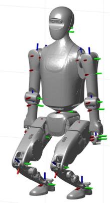
3.6.1 Joint Zero Positions
- Walker Tienkung · Embodied Intelligence
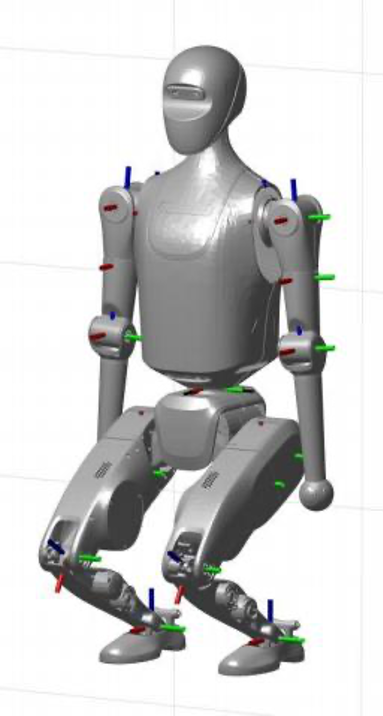
- Walker Tienkung · Voice & Vision
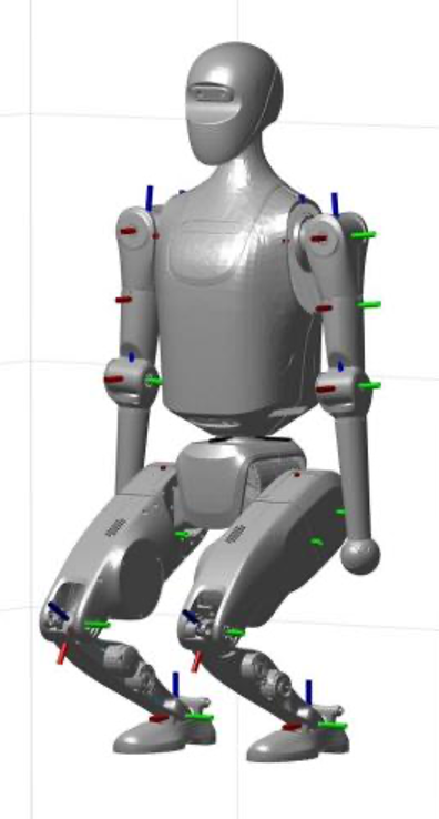
- Walker Tienkung
3.6.2 Robot Global Coordinate Frame
- Global X axis (Roll): the forward direction of the robot is defined as the positive direction.
- Global Y axis (Pitch): the left side of the robot is defined as the positive direction.
- Global Z axis (Yaw): the upward direction of the robot is defined as the positive direction.
The global coordinate frame directions are consistent across all three models.
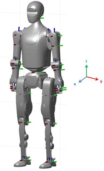
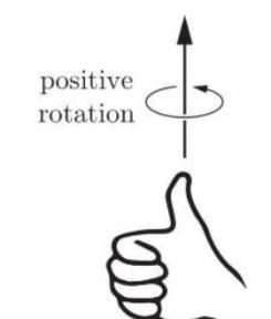
3.6.3 Rotation Axes and Positive Directions
-
For each rotational joint of the robot, the axis direction is determined with reference to the state of the axes shown in the above figure, and is aligned with the positive direction of the robot’s global coordinate frame to identify the positive rotation direction of the joint.
-
Examples:
- For the waist joint, the axis is vertical and close to the global Z axis (Yaw). Therefore, the positive direction of the waist joint axis is upward, and the positive rotation direction of the joint can be determined using the right‑hand rule.
- For the hip Pitch joint, the axis is close to the global Y axis (Pitch). Therefore, the positive direction of the hip Pitch joint is to the left, and the positive rotation direction of the joint can be determined using the right‑hand rule.